DMN Designer
The DMN Designer is a graphical editor for modeling decisions in DMN 1.3 notation. It allows you to create decision diagrams, configure decision tables, define input and output data, and publish decision models to the engine for execution.
Designer elements
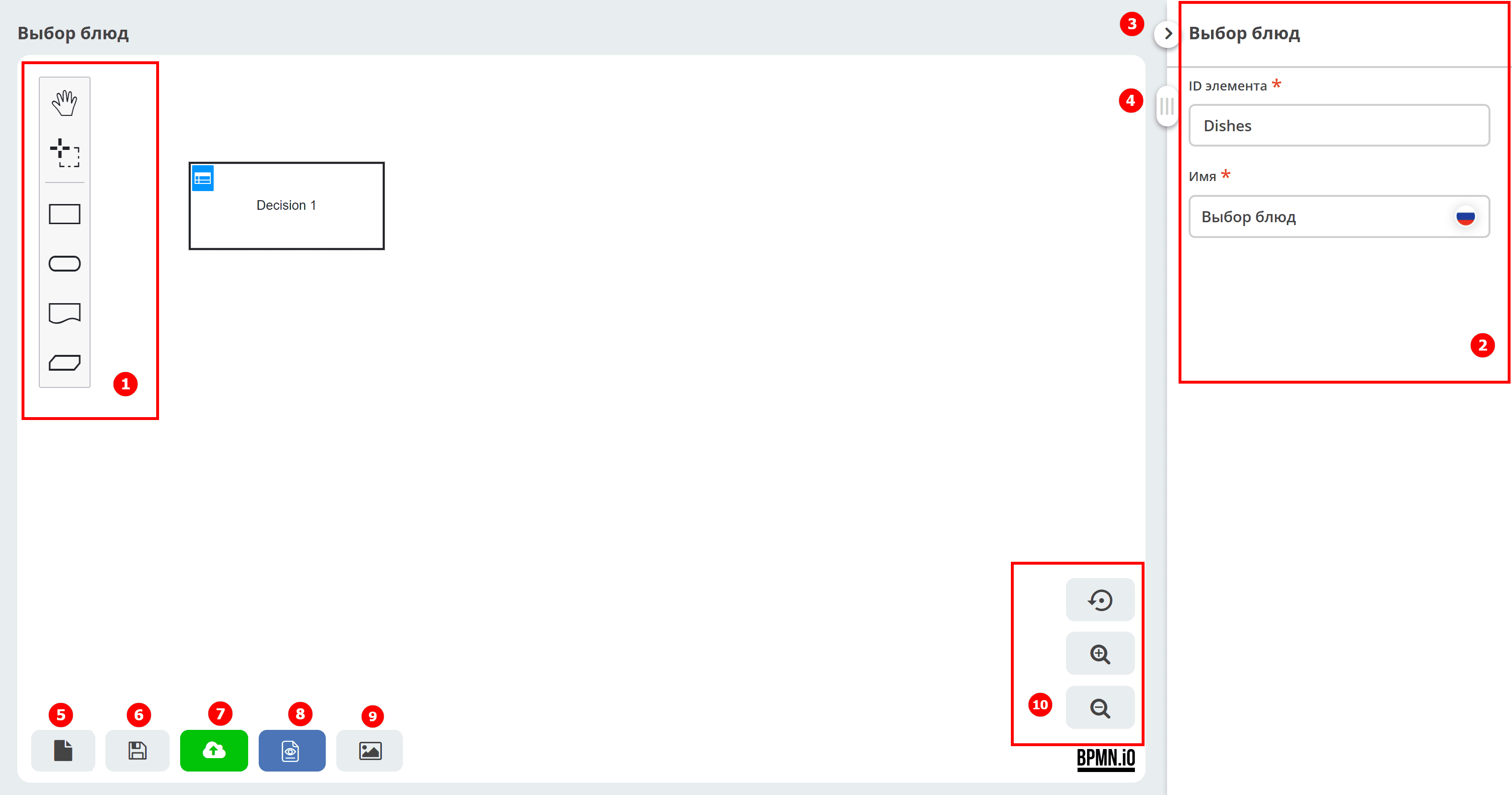
Element panel
Element properties panel – sets the properties of either the entire diagram or the selected element.
Collapse the element properties panel
Slider for moving the workspace
Save process draft
Save process
Save and publish the process to the engine
View process data in XML
Save the process as an SVG image
Zoom control buttons
Element panel composition

|
Activate the hand tool – used to move the diagram up/down or left/right by holding the left mouse button. |
|
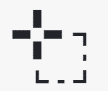
Activate the lasso tool – used to select an area of the diagram, allowing you to select multiple elements by holding the left mouse button.
All elements within the selected area are highlighted.
|
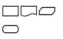
DMN elements

|
Decision – a node in which one or more input elements determine the output based on decision-making business logic defined as an expression or table. |

|
Input data – information used in a decision node or business knowledge model. Input data usually includes business-level concepts or objects related to the business. For example, credit applicant data from a customer application. |

|
Knowledge source – external entities, documents, committees, or policies that govern the decision or business knowledge model. Knowledge sources are references to real-world factors, not executable business rules. For example, a loan application. |

|
Business knowledge model – a reusable function with one or more decision elements. Decisions that share the same logic but depend on different supporting inputs or decisions use business knowledge models to determine which procedure to follow. |
See details in Citeck DMN Components
You create a DMN diagram by selecting the required elements from the Element panel and connecting them with control flows. When you select any element in the diagram, a button panel appears to its right.
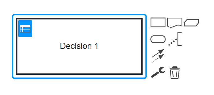
The panel next to the element contains the following buttons:
|
Create the next diagram element linked to the selected control flow |

|
Add annotation text to the element |

|
Connect the element to any other in the diagram |

|
Change element type
Click to change the element type, then select the appropriate type.
|

|
Delete element |