Business Process Designer
Business Process Designer is a graphical editor for modeling processes in BPMN 2.0 notation. It allows you to create business process diagrams, configure element properties, validate the diagram, and publish the process to the engine for execution.
Designer Elements
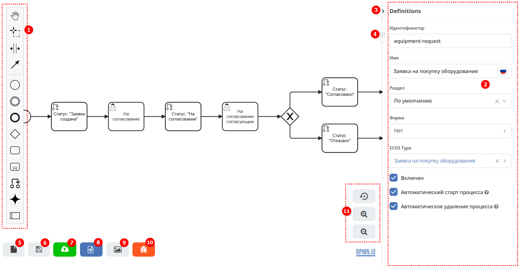
Elements Panel
Element Properties Panel - sets properties for either the diagram itself or the selected element.
Collapse Element Properties Panel
Slider for moving the workspace
Save Process Draft
Save Process
Save and Publish Process to Engine
View Process Data in XML
Save Process as Image in SVG Format
Enable/Disable Error Display
Zoom Control Buttons
Elements Panel Composition

|
Activate the hand tool – used to move the diagram up-down, left-right by holding the left mouse button. |

|
Activate the lasso tool – used to select an area of the diagram - allows selecting multiple diagram elements by holding the left mouse button.
All elements within the selected area are highlighted.
|

|
Activate the create/remove space tool – allows ‘spreading out’ or ‘compressing’ the diagram: place the mouse pointer on the part of the diagram you want to adjust.
And by holding the left mouse button, move that part of the diagram to the desired location.
|

|
Activate the global connect tool - connecting elements: sequence flow (solid line) and message flow (dashed line).
|
Sequence Flow Elements

|
Create StartEvent - initial event |

|
Create Intermediate/Boundary Event - intermediate event |

|
Create EndEvent - final event |

|
Create Gateway - fork or gateway, a logical operator |

|
Create Task – task |

|
Create expanded SubProcess – multiple tasks grouped into a separate sub-task |

|
Create Set document status – changing the status value of a business process element |

|
AI Task — a task responsible for calling AI based on a specified prompt.
|

|
Create Pool/Participant – pool, used to delineate responsibility between tasks, organizations, users.
Pools interact with each other only via message flows.
|
Any business process starts with a start event and ends with an end event. See details: Citeck BPMN Components
You create a BP diagram by selecting the required elements from the Elements Panel and connecting them with sequence flows. When any diagram element is selected, a button panel appears to its right:
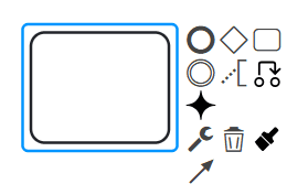
The following buttons are located on the panel next to the element:

|
create the next diagram element connected via a sequence flow to the selected one |

|
add annotation text to the element |
|
|
change the status value of the business process element |
|
|
|

|
change element type
Click to change the element type and then select the appropriate type.
|

|
delete element |

|
change element color |

|
connect the element to any other on the diagram |
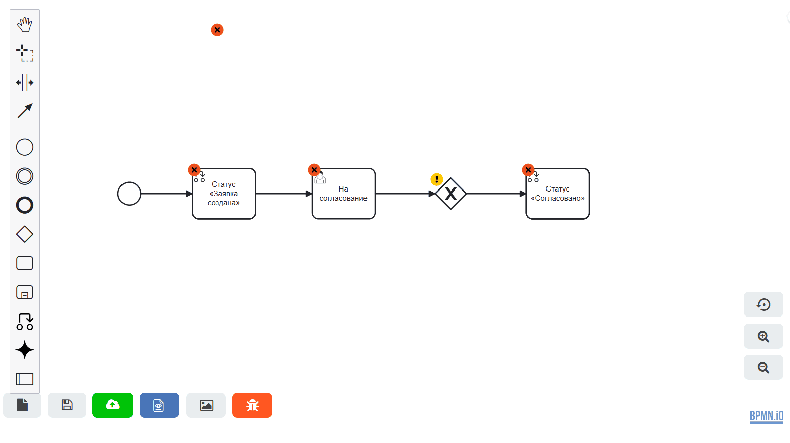
Displaying Errors on the Business Process Diagram
An error display mode (linter) is implemented to inform about errors in the business process diagram. The bpmnlint plugin is used.
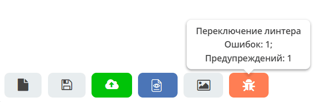
The mode is enabled/disabled by the button:

Hovering the mouse over an error/warning icon shows the error/warning text:
The total number of errors and warnings for the process is shown when hovering over the linter button:
Important
A process with identified warnings can be saved and published. Warnings are based on best practices.
Errors in Process Modeling
Note
Possible process element errors are described in the relevant sections.
Name |
Type |
Description |
|---|---|---|
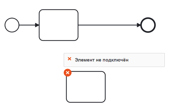
Element not connected |
Error |
Checks if the element is connected to other process elements via incoming or outgoing sequence flows.
Example of incorrect rule usage:
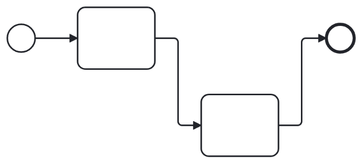
Example of correct rule usage:
|
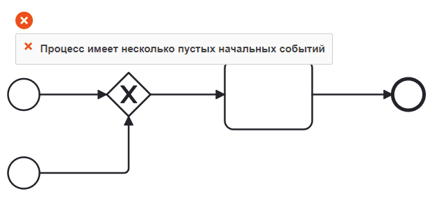
Process/Sub-process has multiple empty start events |
Error |
Checks for only one empty start event per process (or sub-process).
Example of incorrect rule usage:
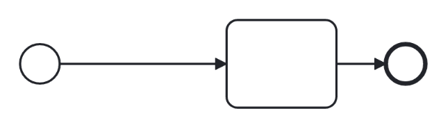
Example of correct rule usage:
|
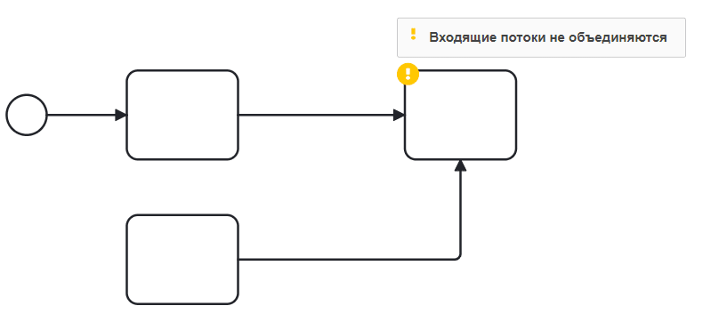
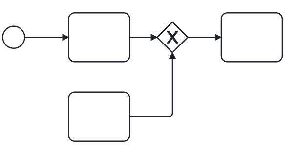
Incoming flows do not merge |
Warning |
Users should model a parallel gateway to achieve the desired behavior.
Example of incorrect rule usage:
Example of correct rule usage:
|
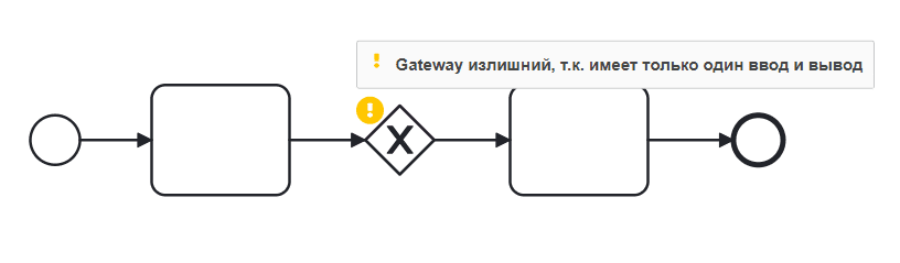
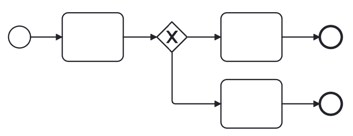
Gateway is redundant as it has only one input and output |
Warning |
A rule checking if a gateway has only one input and output. Such gateways are redundant as they serve no functionality.
Example of incorrect rule usage:
Example of correct rule usage:
|
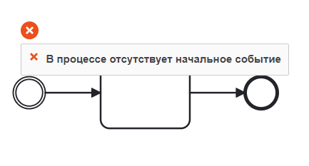
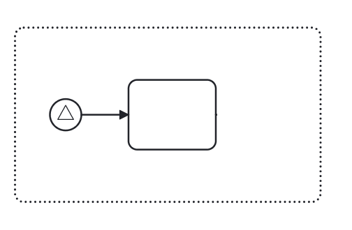
Process/Sub-process lacks a start event |
Error |
Checks for a simple start event in a process or sub-process (non-event-based).
Example of incorrect rule usage:
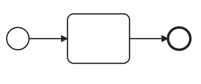
Example of correct rule usage:
|
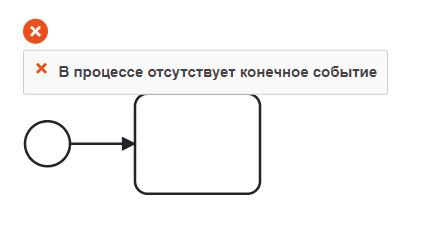
Process/Sub-process lacks an end event |
Error |
Every process and sub-process must have an end event.
Example of incorrect rule usage:
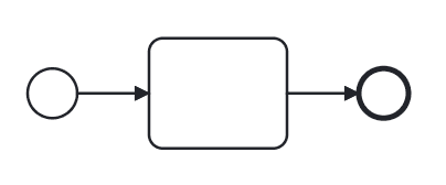
Example of correct rule usage:
|
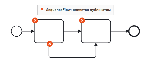
SequenceFlow: is a duplicate |
Error |
Checks that sequence flows are not duplicated. Duplicating sequence flows leads to unintended branching.
Example of incorrect rule usage:
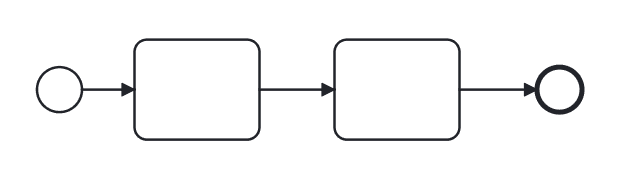
Example of correct rule usage:
|
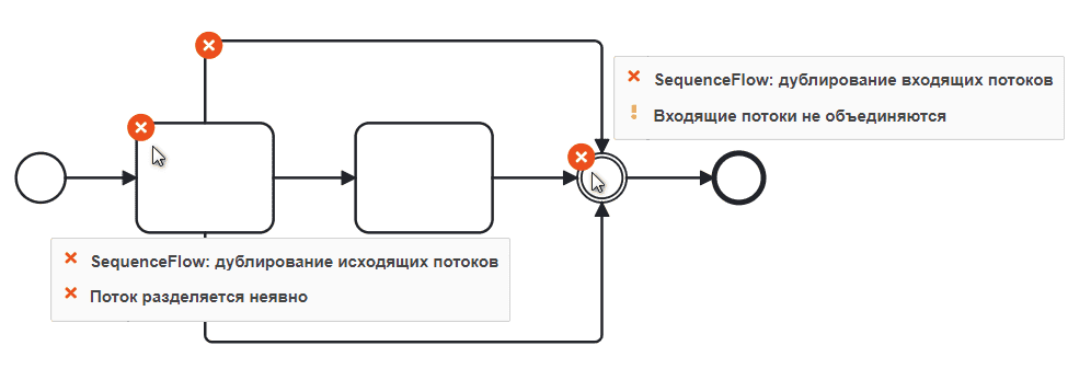
SequenceFlow: duplication of incoming/outgoing flows |
Error |
Checks that sequence flows are not duplicated. Duplicating incoming/outgoing sequence flows leads to unintended branching.
Example of incorrect rule usage:
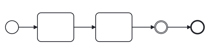
Example of correct rule usage:
|
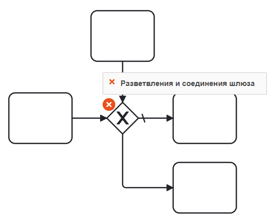
Gateway branching and merging |
Error |
A rule that checks if a gateway both branches and merges simultaneously.
Example of incorrect rule usage:
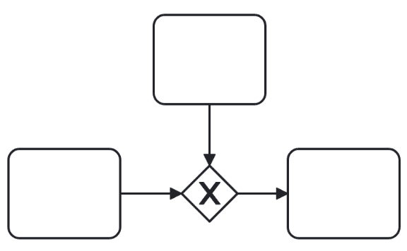
Example of correct rule usage:
|
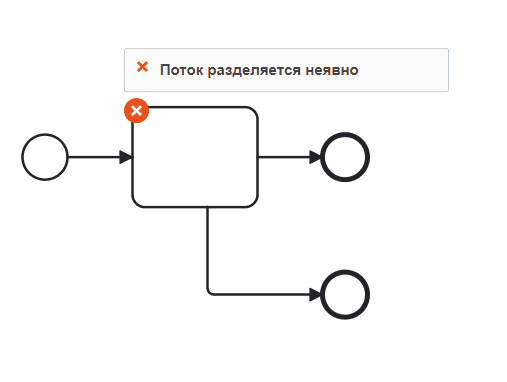
Flow splits implicitly |
Error |
Checks if implicit splitting after a task is being modeled. Instead, users should explicitly model a parallel gateway.
Example of incorrect rule usage:
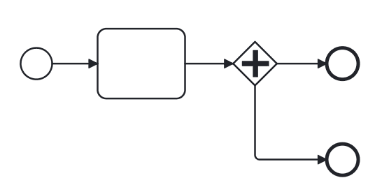
Example of correct rule usage:
|
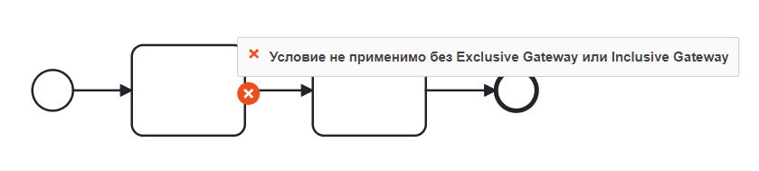
Condition not applicable without Exclusive Gateway or Inclusive Gateway |
Error |
Checks if a sequence flow without an Exclusive Gateway or Inclusive Gateway has a condition type set.
|
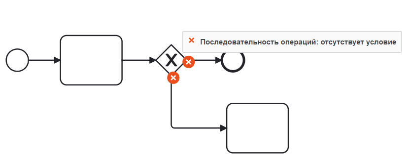
Sequence Flow: missing condition |
Error |
Checks for the presence of a condition type on a sequence flow exiting an Exclusive Gateway or Inclusive Gateway.
See details: condition types
|
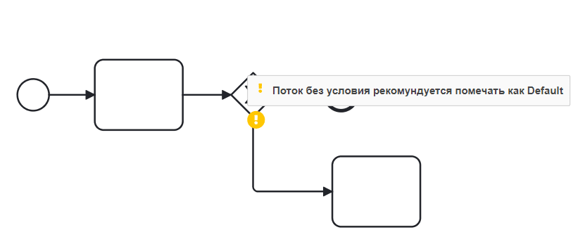
Flow without condition should be marked as Default |
Warning |
Checks if multiple sequence flows exit exclusive and inclusive gateways, and if one flow has Condition Type = None, then such a flow should be marked as default.
See how to change sequence flow type
|
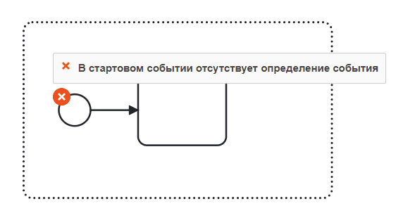
Start event lacks event definition |
Error |
Start events inside event sub-processes must be typed (have an event definition), as required by the BPMN 2.0 standard.
Example of incorrect rule usage:
Example of correct rule usage:
|
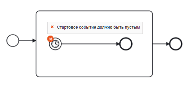
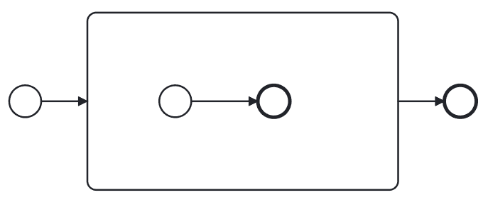
Start event should be empty |
Error |
Checks that the initial (start) event inside a regular sub-process is empty (has no event definition).
Example of incorrect rule usage:
Example of correct rule usage:
|
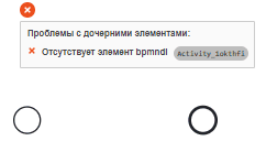
Missing bpmndi element |
Error |
Checks for the absence of BPMNDI information for BPMN elements that should have a visual representation.
Each BPMN element (which requires visual representation) is referenced by a BPMNDI element that defines how to visually display the corresponding element.
It might happen that a user accidentally deletes such a BPMNDI element (e.g., by working directly with XML). This can lead to errors, as the BPMN element would still be interpreted during process execution but would no longer be visible in graphical modeling tools.
Error example:
|